The Practical Utility of Polar Graph Square Graph Paper for Technical Professionals
In an era dominated by software simulations and digital rendering, the tactile, immediate nature of dedicated paper tools remains surprisingly resilient. For a specific cohort of thinkers—engineers sketching preliminary designs, students internalizing trigonometric concepts, makers plotting enclosures, or artists exploring geometric constraints—a specialized sheet does more than a blank canvas. The Polar Graph Square Graph Paper represents a considered attempt to bridge two core visual languages in a single physical volume. It merges a precise radial plotting system with a conventional Cartesian grid, creating a hybrid workspace that addresses the practical fragmentation often found in standalone graphing pads.
What makes this particular collection worth examining is not the novelty of polar graphs themselves, but the deliberate integration of specifications aimed at reducing friction during iterative design. A standard polar grid often leaves a void of wasted space beyond its circumference. By filling that void with a high-density square grid, the paper acknowledges a realistic workflow: calculations and rough ideation rarely stay confined to one coordinate system. This dual-format approach targets a persistent practical need for a unified planning surface that supports both angular symmetry and rectilinear refinement.
Precision Architecture and the Radial Coordinate System
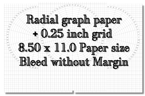
The core of the product rests on its radial framework. A maximum circle diameter of 7.50 inches sits centered on the standard 8.5 x 11.0 inch sheet, establishing a substantial plotting area without encroaching on the margins. The radius extends to 3.75 inches, marked clearly in quarter-inch increments. For seasoned graph users, a 0.25-inch radial step offers an effective resolution. It is granular enough to capture nuanced amplitude changes in signal patterns, yet spaced sufficiently to prevent visual clutter when plotting by hand.
Angular demarcation is where the precision truly asserts itself. The paper marks degrees at three tiers of frequency: every single degree, every 5 degrees, and every 15 degrees. This hierarchical visual density serves distinct cognitive purposes. The fine 1-degree hash marks provide absolute resolution for high-precision optical alignment or auditory transduction diagrams. The mid-level 5-degree markings enhance legibility when sketching common mechanical offsets or architectural sightlines. The bold 15-degree intervals—anchoring the 0°, 90°, 180°, and 270° axes—offer immediate orientation for rapid symmetrical sketches. This tri-level marking system minimizes the mental overhead of counting tiny lines, allowing the user to rely on visual weight to navigate the disc quickly.
Balancing Radial Data with Rectilinear Sketching
A distinguishing feature is the treatment of the paper’s balance. Beyond the 7.50-inch circular boundary, the remaining area of the sheet is ruled with four squares per inch graph. This is a smart allocation of real estate. When drafting a phased array or an antenna radiation pattern in the polar region, an engineer invariably needs to scribble impedance calculations, component values, or mechanical tolerance notes in the margin. Providing a structured, fine grid for these annotations prevents the drift and misalignment that occur on blank or lined paper.
This 4x4 quad grid effectively doubles the paper’s utility. A designer might plot an acoustical dispersion lobe within the circle, then use the surrounding Cartesian grid to draw an exploded view of the driver housing or a circuit diagram for the crossover network. This continuity prevents the need to switch between a polar pad and a separate engineering pad, keeping the creative momentum intact. The transition between coordinate systems is seamless, contained within a single leaf of acid-free-style stock that accepts pencil and fine-tip ink without bleed-through.
Format Flexibility and the PDF Workflow Advantage
The delivery mechanism matters just as much as the physical layout. The offering specifies a 120-page PDF format. For a resource like Polar Graph Square Graph Paper, PDF distribution translates into a profound long-term value proposition. Users gain immediate access without inventory lag. More importantly, they gain control over reproduction. An engineering student entering a capstone project may exhaust dozens of sheets in a single week. The ability to print a fresh leaf on demand, selecting only the required page range, eliminates the hesitation of wasting an expensive physical pad on exploratory thoughts.
Printing parameters are optimized for the 8.5 x 11.0 inch home and office standard. Users can test various paper substrates; a heavyweight 32 lb bond provides a luxurious drafting feel with excellent erasability, while a lighter 20 lb stock keeps bulk printing economical for quick problem sets. The fixed PDF ensures the precise 7.50-inch maximum diameter and the exact registration of the 1/4-inch radius increments never shift from print to print, maintaining a calibration constant that is critical for scaled physical templates used with calipers or mechanical dividers.
Evaluating Performance for Design and Engineering
In a practical design loop, whether for a PCB board shape, a cycloidal drive prototype, or a lighting fixture reflector, the tool’s strength lies in its predictability. The concentric circles, anchored to a solid center point, facilitate immediate symmetry checks. If a user draws a cam profile at a base radius of two inches and a peak lift of three inches, the 1/4-inch graduations make the displacement visible without requiring a ruler for every mark. The dense 1-degree ticks around the perimeter assist in defining dwell angles with acceptable real-world tolerance.
However, the paper is a static medium; it does not constrain the hand or correct errors. The 1/4-inch resolution is generous for macro mechanical sketches but might feel sparse to a user drafting miniature microfluidics between a 0 and 1-inch radius. In such cases, the 4-squares-per-inch background grid in the outer zone cannot rescue the inner polar zone’s fixed step. The 7.5-inch diameter also imposes a strict circular boundary. An antenna designer analyzing a pattern that requires a -20 dB null far beyond the normalized limit may need to draw a smaller normalized circle within the grid, effectively sacrificing the outer radius marks. Yet, in standard product design and academic demonstrations, the scale is well-matched to the sheet size, leaving generous header and footer space for title blocks and date entries without crowding the polar data.
Who Gains the Greatest Advantage
The primary audience spans distinct but overlapping technical domains. Electrical engineers dealing with Smith charts or antenna topologies will find the angular precision indispensable. The 1-degree marks align well with the resolution needed for phase angle calculations. Mechanical design engineers prototyping cams, gears, or rotary indexing tables can treat the concentric rings as instant reference diameters, directly transferring caliper readings onto the pre-drawn geometry.
Engineering students, particularly those wrestling with complex plane analysis, control systems root locus, or wave interference patterns, gain an external working memory. The paper reduces the cognitive load of manually dividing circles, enabling faster iteration on problem sets. The 120-page depth ensures that a single digital purchase covers multiple semesters. Educators and tutors benefit from the clarity of the pre-printed degrees. When demonstrating the concept of phasor rotation on a document camera, the bold 15-degree marks remain visible on compressed video feeds, while the finer 1-degree marks allow students following along on a tablet to achieve high-fidelity copies.
Beyond the strictly technical, serious hobbyists and crafters—those working on segmented wood turning, mandala symmetry, or knitted radial patterns—find the combination of polar and square grids a low-cost scaffolding device. A costume designer laying out a concentric skirt panel can draft the pattern in the polar zone and calculate fabric yield using the grid in the margins.
Integrating the Tool into a Professional Workflow
To use the Polar Graph Square Graph Paper effectively, treat it as the second step in a three-step process: ideation, drafting, and digitization. Begin with a rough concept stroke on the outer grid, define the critical circumferences using the quarter-inch rings, then refine the precise angular targets. The PDF format encourages printing a batch of sheets for a specific project, clipping them to a drawing board, and treating them as disposable but precise scratchpads. Once the form feels right, the sketch serves as a clear source for tracing into a vector software environment like AutoCAD or Fusion 360 for dynamic simulation. The legible 7.5-inch diameter scans cleanly on flatbed scanners, with the 4x4 grid providing sufficient background contrast for high-fidelity image capture without overwhelming the primary polar trace.
Understanding the Physical and Digital Constraints
No single stationery solution eliminates all friction. The PDF format, while convenient, relies entirely on the user’s printer accuracy. A poorly calibrated office laser printer suffering from drum warping or skewed paper pickup may introduce a minor geometric distortion, subtly stretching the circles into ellipses. Before relying on a printed sheet for a tight-tolerance mechanical template, users should verify the X-Y dimensional accuracy with a calibration test print. Additionally, the digital nature prohibits the tactile luxury of a gum-bound pad that tears away cleanly; the user must manage loose sheets, which demands a disciplined filing system or a sturdy clipboard to prevent loss of critical sketches on a cluttered workbench.
The specification of four squares per inch, while a common drafting standard, yields a line weight that can compete visually with the polar radii if a user writes with a heavy hand or a soft 2B pencil. Switching to a harder lead (2H or 4H) for the Cartesian annotations and reserving a softer HB lead for the polar trace maintains visual hierarchy. The absence of logarithmic radial spacing confirms this paper is targeted at linear, geometric, and trigonometric applications rather than specialized RF impedance matching tasks that demand a log-scale polar chart. Recognizing this scope prevents misapplication and wasted effort.
The Lasting Value of a Well-Measured Hybrid
The staying power of a resource like this depends on how often a professional reaches for it, bypassing a digital analysi s tool for a quick manual verification. In the compressed timeline of a client meeting or a rapid prototyping sprint, sketching a quick antenna beamwidth overlay or a planetary gear layout by hand remains faster than constructing a parametric model from scratch. The prepared 120-page archive provides a long horizon of availability; it is a resource that does not expire with a subscription cycle or a software version update.
For the analytical mind, the combination of 0 to 360 degrees marked at three distinct intervals, quarter-inch radial increments, and a dense Cartesian margin translates to a tangible thinking medium. The Polar Graph Square Graph Paper does not aim to replace computational electromagnetic solvers or 3D constraint-driven sketchers; instead, it fills the quiet gap where intuition and hand-eye coordination still drive the first draft of innovation. Its practical value hinges on this seamless switching between the rotational and the orthogonal, all captured within the familiar confines of a letter-size sheet.